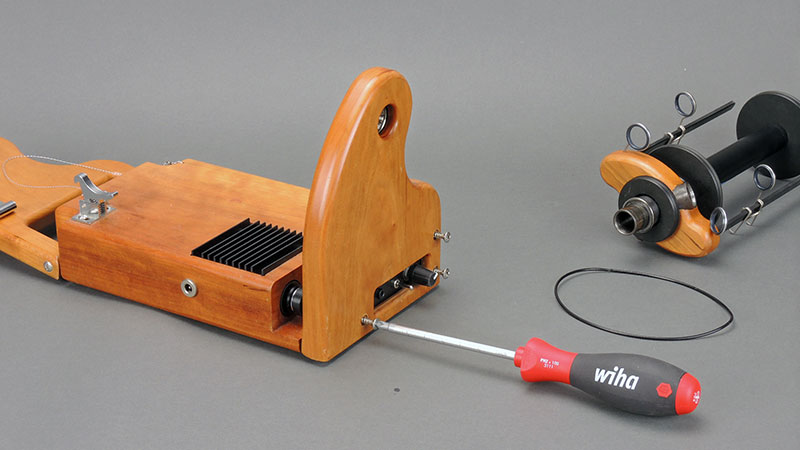
Remove the drive band and flyer, then unscrew the three (3) screws holding the face to the base of your miniSpinner.
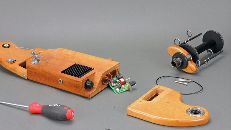
Pull the controller out of its pocket and turn it over.
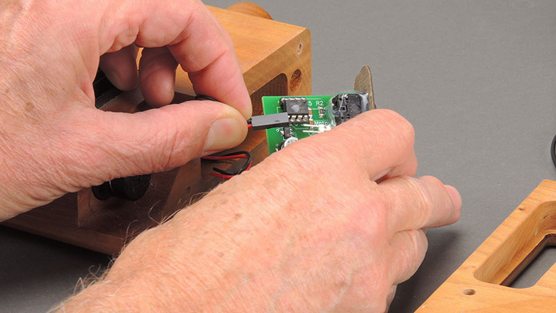
Remove the two connectors from the headers on the circuit board by pulling them off. This is a good time to mark the POWER connector with a spot of nail polish or tape so you know which is which when you reconnect the wires later.
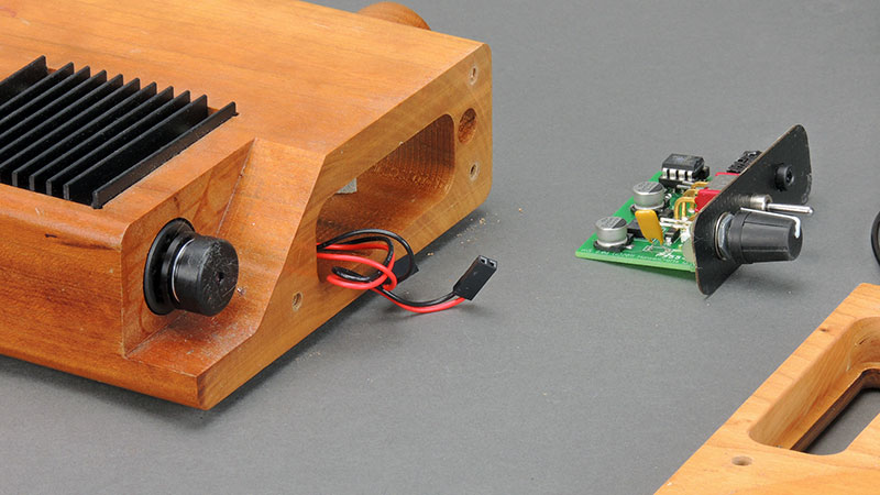
Set the controller board aside. You may see a shim, usually foam tape, in the bottom of the circuit board pocket in the base. This holds the board forward against the cutout in the face of your miniSpinner.
Remove the three small screws from the heat sink. Note that one screw is missing. This is intentional because there is nothing beneath the hole for the screw to engage.
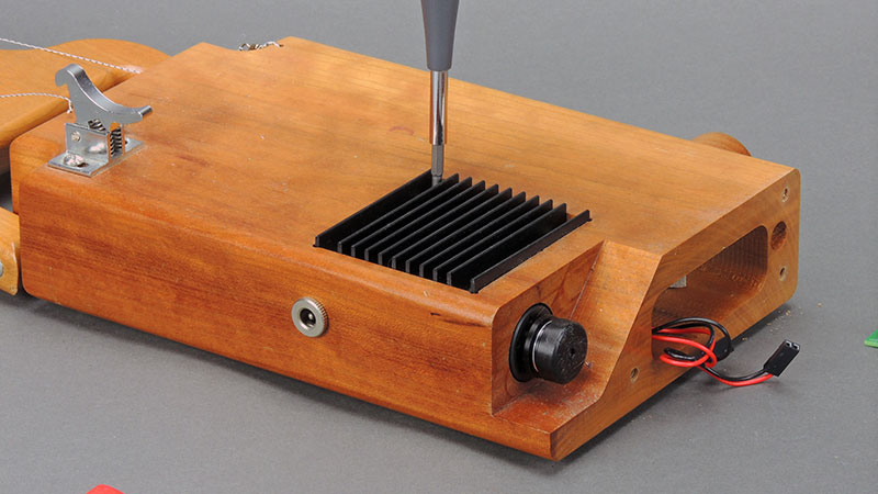
A view of the heat sink with the screws removed.
Grasp the heat sink by the inner edge and pull it up as shown. It may be a tight fit, plus it is adhered to the motor with a piece of double-stick, thermally conductive tape.
Set the heat sink and screws aside, gently pull the motor's wires out of the hole leading to the controller, and pull the motor out of the front of your miniSpinner.
The new motor and a new piece of thermally conductive double-stick tape.
Insert the new motor back into the base, then thread the wires into the circuit board pocket. The front of the motor should be flush with the wood, as shown here.
Peel the plastic from the blue side of the thermal tape and apply it on the top of the motor, then remove the plastic from the white side of the tape.
Double-check to ensure the motor is flush with the face, then reinstall the heat sink. The double-stick tape should hold the motor in place when it sticks to the bottom of the heat sink. Once the heat sink is screwed down, turn your miniSpinner over, insert the 3/32" Allen wrench (from the bag attached to the instructions) into the hole beneath the motor and GENTLY snug up the screw beneath the motor. This holds the motor tight against the heat sink so it will remain in place.
Now reconnect the wires to the controller board. Note that the RED wire goes to the + terminal.
Both connectors should have the RED wire on the same side, as shown here. Press them on all the way.
Turn the controller board upside down and place it into its pocket. Be sure the wires are not trapped between the back of the controller board and the bottom of the pocket; this would prevent it from going all the way into the pocket.
Place the front back on your miniSpinner and gently snug up the screws. It usually helps align the controller if you pull the knob towards the front to seat it into the pocket in the rear of the face piece. Don't tighten the screws all the way yet.
Check that the face fits tight against the base. If there is a gap, remove the three screws and check to see that a wire isn't caught behind the controller or between the wood face and the base piece. DO NOT FORCE IT! If you cannot get the face to seat snugly with a reasonable amount of pressure, contact support@hansencrafts.com for advice.
