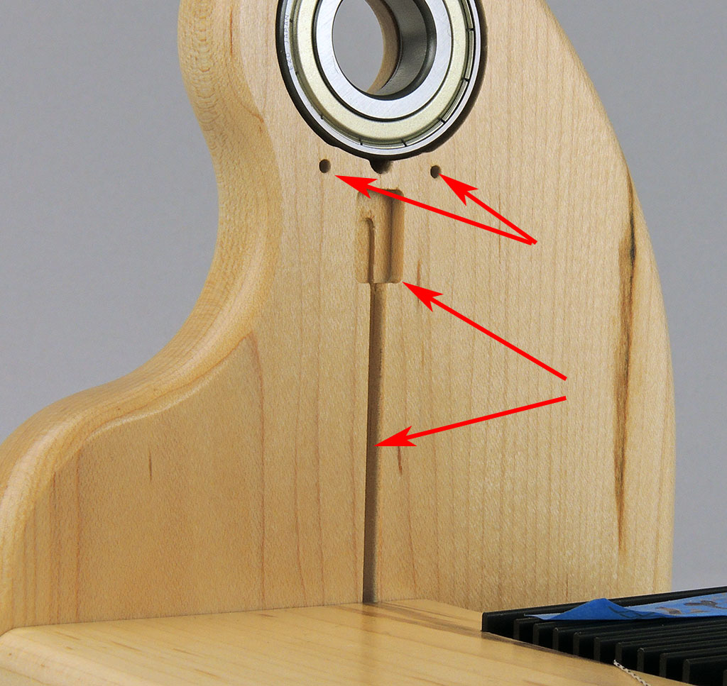
The tach sensor is a small circuit board installed just below the ball bearing of your miniSpinner. Current miniSpinner Classics are ready for this add-on, with holes drilled and wire channels already cut as shown by the arrows in the photo below.
Early miniSpinners lack these holes and wire channels, and should be returned to HansenCrafts to have the sensor installed; we'll drill the holes and cut the wire channels as part of the process, at no charge to you.
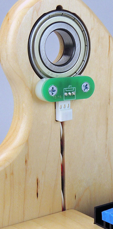
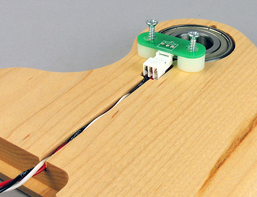
Remove the face of your miniSpinner and install the sensor as shown here. Note the orientation of the circuit board and the spacers beneath it. Push the wires into the wire channel.
Next, plug the sensor cable into the circuit board as shown by the red arrow.
(You can also see the plastic rods that hold the controller up against the faceplate at the sides of the pocket, as well as the steel locating pins to align the face with the base.)
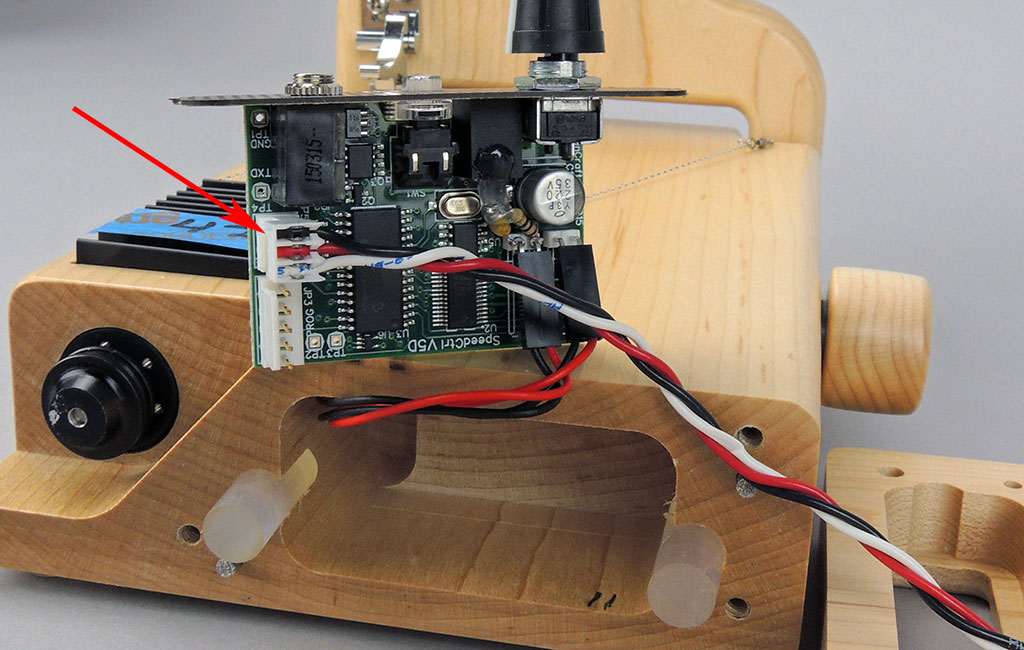
Route the wires around the circuit board as shown.
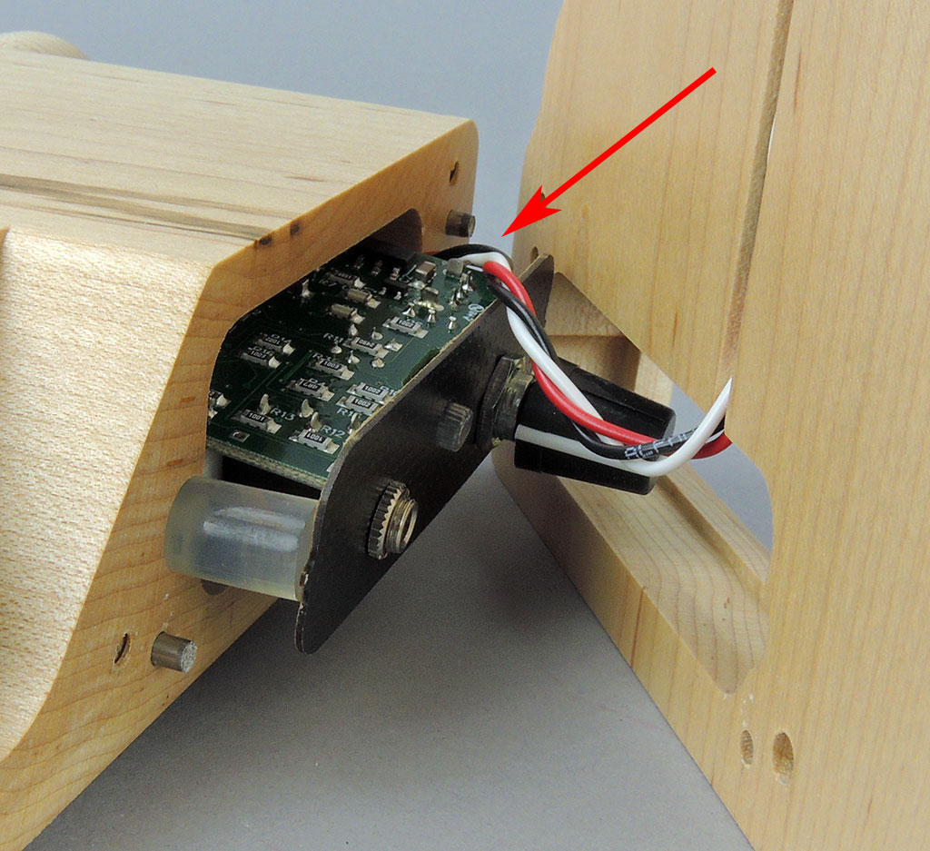
Next, move the circuit board into the pocket in the rear of the faceplate, and tuck the wire in so it is contained inside the pocket and not crushed between the face and the body when you screw on the face. Carefully put the assembled parts into place, noting that the plastic rods fit into the little channels cut for them in the face pocket. These will push the circuit board's faceplate tight against the front of the pocket in the face of your miniSpinner.
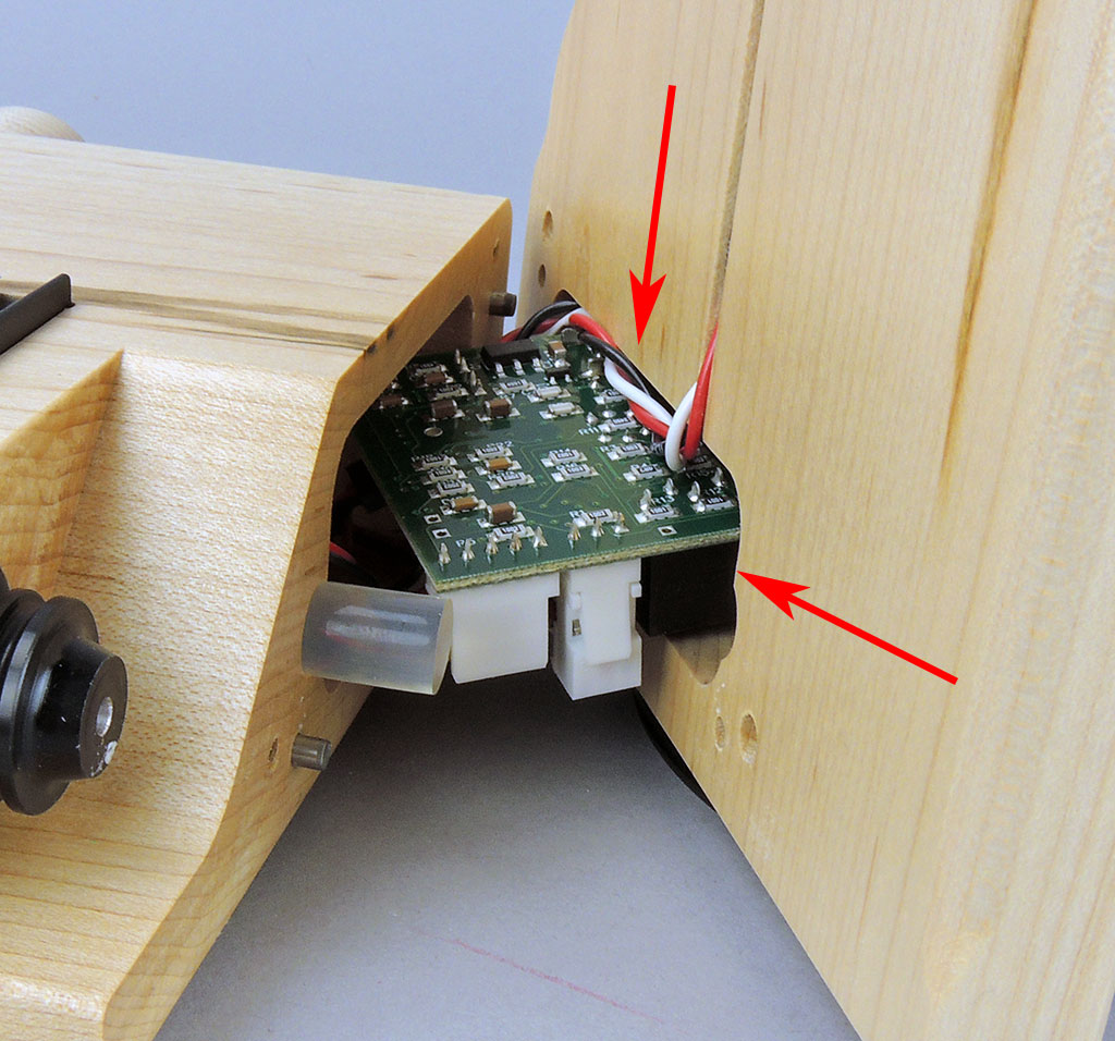
Carefully screw the face into place, making certain the wires are not pinched between them. You're done!
